Introduction:
The relay is widely used in automotive electronics in the current circuit of consumers where a lot of current flows. The higher the current, the thicker the wiring needs to be. The diameter of the wire determines the maximum permissible current. We want to avoid thick wires as much as possible, because otherwise wiring looms become too large and prone to faults. A second, and even more important reason to use relays is the control by an ECU. High current is accompanied by more heat. We want to keep this heat outside the ECU as much as possible. Examples of electrical components that are controlled by a relay include:
- Engine cooling fan;
- Horn;
- Rear window defogger;
- ECUs;
- Injectors and ignition coil (petrol engine);
- Fuel lift pump;
- Dipped beam, main beam and / or fog lights.
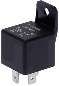
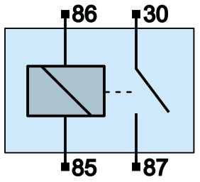
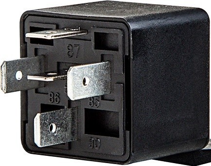
The next two images show a diagram of the relay and a picture of a real relay. On the relay we find four connections with standard DIN codings:
- Control current input (86)
- Control current output (85)
- Main current input (30)
- Main current output (87)
A relay converts a small control current into a large main current. That is a standard phrase many students and technicians can recite. When it comes to measuring a relay circuit, people often get confused by the codings: where does the control current flow and where the main current? And how should you measure to check whether the relay is working properly? The following paragraphs describe how the relay works, which voltages you should measure on a properly functioning relay and how to search for faults.
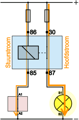
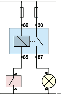
The images below show a de-energised and an energised relay.
- Relay de-energised:
The switch (red housing) is located in the diagram between the output of the relay (terminal 85) and the battery ground (body). In reality, this switch may be located in the dashboard, for example the fog light switch. - Relay energised:
When the driver operates the switch, the contacts close. This closes the current circuit on the control-current side. Current flows from the positive terminal of the battery, through 86, the relay coil, and via 85 and the switch to ground. Because current flows through the coil, it becomes magnetic and pulls the little switch between pin 30 and 87 closed. A closed current circuit is now created there as well. A main current flows via the positive terminal of the battery, through the fuse to terminal 30 of the relay, after which the current is supplied via terminal 87 to the consumer. The consumer switches on.

In the images, a lamp is often shown as the consumer. In reality, of course, other electrical loads / actuators can be used. For a relay circuit it does not matter what type of consumer is being controlled.
The control current through a relay is usually between 150 and 200 mA (0.15 – 0.2 A). The main current can rise to 20 or 50 A. The maximum permissible main current is often stated on the relay housing.
Relay circuits:
With a relay, a control current with a low current strength is switched by a switch that we can operate manually, or by a control unit (ECU). The circuit with the ECU is found in most modern vehicles.
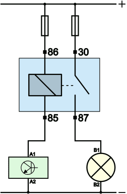
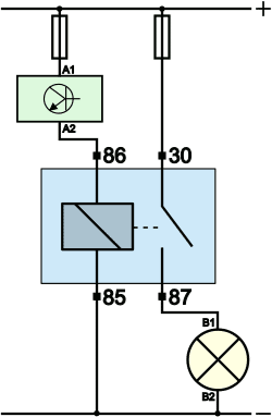
A relay can be switched on the positive side or on the ground side. For the operation of a relay, it does not matter whether it is switched on by switching on the supply or the ground: as soon as the relay receives a positive and a negative, current will flow through the coil. The three images below show a ground-side switching with a switch and ECU, and a positive-side switching.
The versions in which a control unit switches the control current on and off offer several advantages:
- The driver can instruct the control unit to switch on the consumer. This can be done with a small switch on the dashboard, or via the digital on-board computer (possibly via the multimedia screen);
- The ECU can switch the relay on and off itself in response to a sensor signal (e.g.: engine temperature high, fan on), or switch off the fuel pump at the moment that an accident is registered by the airbag ECU. Control by the ECU therefore provides comfort, but also a higher level of safety.
In the diagrams in this image, terminal 86 is regarded as the input and 85 as the output. In practice, we regularly see manufacturers reverse these pins: 12 volts enters at 85 and 86 is connected to ground. The relay can then again be switched on the positive or on the ground side. This can often be looked up in the wiring diagram, and otherwise measurements will reveal how the relay is connected in the vehicle.
Measurements with relay de-energised and energised:
The introduction described how the control current and main current are established. When a consumer no longer works, the fault memory is usually read out first and the voltage across the consumer is measured. With a V4 measurement it is possible to trace whether there is a contact resistance or an interruption in the power supply or ground. When a wire is broken, a fuse is defective, or a switch remains in the “open” position, we measure in V3 and/or V4 a value that is not equal to 0 volts: in other words, something is wrong. This paragraph shows example measurements to check the voltages at the relay. We assume the situation where 86 is the input and 85 the output of the control-current side. The previous paragraph explained that manufacturers sometimes reverse this.
Relay de-energised:
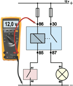
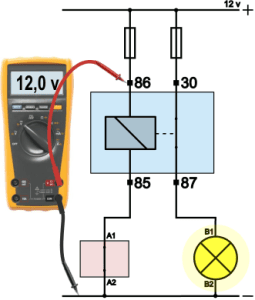
This text refers to the measurements shown in the four images below. With a de-energised relay, we use the multimeter to measure the voltage at the four pins (86, 85, 30 and 87) relative to ground (body or with a crocodile clip on the negative terminal of the battery).
- Measurement 1: at the input of the control-current side of the relay (pin 86) there is 12 volts (or 24 volts in a commercial vehicle);
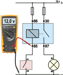
- Measurement 2: with a de-energised relay, the voltage has not been consumed, so it is 12 volts at pin 85;
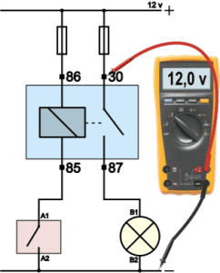
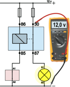
- Measurement 3: at the input of the main-current side (pin 30) there is 12 volts;
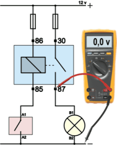
- Measurement 4: because the relay is not energised, the switch in the relay is open, and there is a voltage of 0 volts at pin 87.
| Terminal 86: | 12 v |
| Terminal 85: | 12 v |
| Terminal 30: | 12 v |
| Terminal 87: | 0 v |
Relay energized:
The switch is closed. Terminals A1 and A2 are connected to each other. The control current circuit is closed and a control current is flowing. With the relay energized, we again measure the voltage on the four pins (86, 85, 30 and 87) relative to ground.
- Measurement 1: at the input of the control-current side of the relay (pin 86) there is 12 volts;
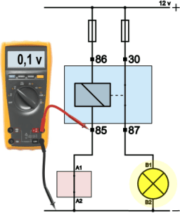
- Measurement 2: with the relay energized, the voltage has been consumed and converted into magnetism, so there is 0.1 volts on pin 85;
- Measurement 3: at the input of the main-current side (pin 30) there is 12 volts;
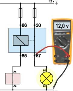
- Measurement 4: because the relay is energized, the switch in the relay is closed, and there is a voltage of 12 volts on pin 87.
| Terminal 86: | 12 v |
| Terminal 85: | 0.1 v |
| Terminal 30: | 12 v |
| Terminal 87: | 12 v |
Fault tracing:
With a malfunctioning consumer / actuator we can measure the voltages at the terminals of the relay to trace the cause of the fault. If a relay does not switch on, the cause may be a defective relay, but if the fuse is blown and the relay does not receive any input voltage, it also cannot switch anything through. With four measurements on the relay (always relative to ground) we can already rule out many things and search more specifically for the exact interruption. In the examples below with possible faults, the red X indicates the location where the fault is situated, and the value shown on the multimeter represents the voltage difference between the measured points.
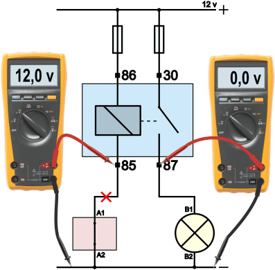
Fault 1: the relay does not switch on
The relay is connected to ground by the switch, but no control current flows. As a result, no main current flows either. The voltage on pin 87 remains 0 volts. That is reason to measure the other pins on the relay. After switching on, the voltage difference between pin 86 and 85 is measured and here 12 volts is measured. In this situation the coil is open-circuited.
The voltage difference across a properly functioning relay is 12 volts, because the voltage is consumed. With this measurement it appears to be in order, but it is not. With an open coil we also measure 12 volts, because a difference of 12 volts is measured between the test leads: 12 volts comes in on the red lead and on the black lead, via the closed switch, there is 0 volts.
When the suspicion arises that the coil in the relay is open, the resistance can be measured. The relay must be removed and may no longer be part of the circuit. On the loose relay terminals we can measure the resistance between pin 86 and 85.
- resistance through the coil: around 60 to 80 ohms: OK
- resistance through the coil: infinitely high (1. or OL): open circuit

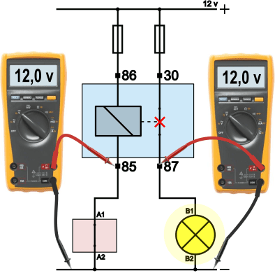
Fault 2: the relay does not switch on
When operating the switch (red housing) or after switching on the ECU, the consumer remains off. With the measurement on pin 85, 12 volts relative to ground is measured. From this we can conclude that the voltage has not been consumed in the coil, so the coil has not become magnetic.
A differential measurement between pin 85 and pin A1 on the switch will show whether the wire is broken, or whether the problem lies in the switch:
- Voltage difference between 85 and A1: 12 volts: wire broken
- Voltage difference between 85 and A1: 0 volts: the problem is not in the wire.
When the wire is in order, there is 12 volts on both sides of the wire, so we measure a difference of 0. If we measure 12 volts across the switch (A1 relative to A2), then the interruption is in the switch. In other words: the switch remains open. We also measure this 12 volts when the switch is not operated.
Fault 3: consumer remains switched on.
A possible customer complaint is that the cooling fan of the vehicle keeps running while the vehicle is parked and has been locked for some time. The customer has noticed this by the sound coming from the fan. Another possibility is that a customer reports a leakage current problem: the battery is always flat after a relatively short standstill, while the condition of the battery and the charging system are in order. In that case we speak of leakage current, or a clandestine consumer.
The measurements show that no control current is flowing (pin 85 has 12 volts), but that a main current is indeed flowing.
In this case the cause is a “sticking” relay switch. The switch between 30 and 87 remains closed even though the coil is not magnetic. The cause may be age, with contacts that have burned in.
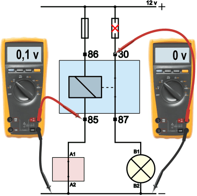
Fault 4: the relay switches on, but the consumer does not function
When the relay is switched on, you will in most cases hear the little switch between 30 and 87 close. Pin 86 has 12 volts and pin 85 has 0.1 volts relative to ground. This means that a control current is flowing and the voltage is being consumed in the coil. The control current circuit is therefore in order.
Pin 30 has 0 volts relative to ground. The relay has closed the main current circuit, but if nothing goes in, nothing can be switched through. In this case the fuse is blown.
A fuse does not blow for no reason. There has been a current through the fuse that was too high, so it is important to look for the cause. For example, there may be too many consumers connected to the fuse (think of multiple 12-volt accessory sockets), or in the past a fuse with an incorrect rating has been installed.
Fault 5: the relay switches on, but the consumer does not function
At the moment the voltages on the four terminals of the relay are in order, you can be sure that the relay is being controlled properly, the input voltages are good and the relay is functioning correctly. The voltage on pin 87 becomes 12 volts when the relay is switched on and returns to 0 volts when it is switched off.
If the consumer still does not work at that point, the likelihood is high that the consumer itself is defective, or that there is a wire break between the relay and the consumer, or between the consumer and ground. A V4 measurement across the consumer will in that case help to determine the location of the fault.
If the voltage across the consumer is equal to the battery voltage, i.e. 12 volts, then the consumer is defective. In this example the filament of the bulb is broken.
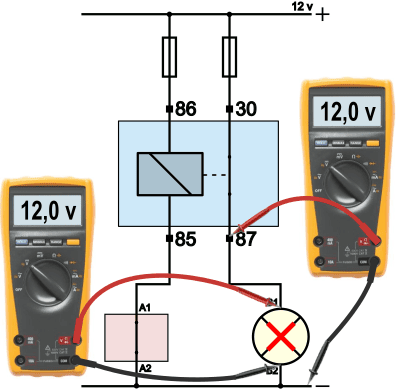
Fault 6: the relay switches on, the consumer operates, but not well enough
The consumer does operate, but at half power. With a lamp, this can be recognised by it glowing dimly, which is especially noticeable when several lamps are on and one differs in light intensity. A consumer can also be an electric motor that runs slowly, or a horn that produces too little sound. In that case, we perform a V4 measurement on the main current section. The relay switches the consumer on, so we do not need to focus on the control current section.
With the V4 measurement in the image at the bottom left, we see that the lamp is operating at 9 volts, while the battery voltage is 12 volts. In the V3 (from battery positive to lamp positive) a voltage difference of 3 volts is measured. This is lost in the positive circuit. Follow-up measurements will show whether the voltage loss occurs before the relay, in the relay or after the relay (between pin 87 and B1). In the image at the bottom right, it can be seen that the voltage difference across the relay (30 compared to 87) is 3 volts. The voltage loss occurs in the relay. The contacts of the small switch are contaminated or burned in, causing a contact resistance to form.


Summary:
Due to the extensive fault descriptions and the large images, this section provides a summary of the different faults with their causes:
- fault 1: the relay does not switch on because the relay coil is interrupted. No current can flow through the coil anymore, so the coil can no longer become magnetic. A resistance measurement can be used to trace the break: around 60 to 80 ohms is fine; infinitely high means an interruption;
- fault 2: the relay does not switch on because the wire between pin 85 (control current output) in the switch is interrupted. In that case, the voltage at pin 85 remains 12 volts, even when it is switched on;
- fault 3: the relay sticks, causing the consumer to remain switched on. The voltage at pin 87 remains 12 volts, even when the relay is not activated. This can be noticed because it is seen or heard, but with a “silent” (parasitic drain) by an consumer, the battery is drained;
- fault 4: the relay switches on, but due to a defective fuse the consumer does not operate;
- fault 5: because the consumer is defective, it no longer operates. With the four measurements on the relay, it has been ruled out that the cause lies in the control;
- fault 6: contact resistance causes a poorly operating consumer / actuator. With the V4 measurement, the location of the contact resistance can be traced. In the example, a voltage difference is measured across the small switch between 30 and 87, which shows that there is voltage loss as a result of the contact resistance in the relay.
Conclusion:
With the six possible fault causes that we can encounter in vehicles, it has been demonstrated how important the knowledge and skills are to measure the voltages at the relay. Measuring the four terminals quickly provides a direction for troubleshooting, and it quickly becomes clear whether something goes wrong in the control current input or output, the main current input or output, or inside the relay itself.
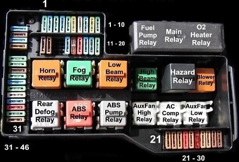
Locations of relays:
Relays are often mounted in one place in the car. This can be in the fuse box (as in the image) or on a separate relay board. There may also be additional relays mounted in the engine compartment, such as the relay for the engine cooling fan. The relay positions can be found in the owner’s manual and/or the workshop documentation of the car.